twoWayTraveltime2depthコマンド マニュアル

(The documentation of twoWayTraveltime2depth command)

Last Update: 2022/9/1


◆機能・用途(Purpose)

往復走時を深さに変換する。
Convert two-way traveltimes to depths.


◆概要(Overview)

このプログラムは反射断面の推定を主に念頭に置いて作成したものである。 反射断面の推定ではまず時間の関数としての反射応答の推定が行われる。 このプログラムでは反射応答における独立変数の「時間」を 地表から鉛直下方に射出された波が 地下で反射して地表に戻ってくるまでの所要時間(往復走時)であると見なし、 1次元速度構造のもとで反射点の深さに変換する。 山岳地域の浅部構造を求める場合など観測点の標高を無視できない場合を想定し、 深さの代わりに標高に変換することもできる仕様にしている。
This program was developed mainly bearing in mind a reflection survey, in which a reflection response as a function of time is first estimated. This program regards the independent variable “time” of this reflection response as the time neded for the wave to propagate downward from the ground surface, reflect at a subsurface reflector, and return back to the surface (two-way travel time). Based on this assumption, the program converts time to the corresponding depth of the reflector. Instead of the depth, this program can convert the time to altitude, bearing in mind an application to shallow subsurface structure beneath a mountain region where station altitudes are not negligible.


◆ソースコード(Source code)

$YMAEDA_OPENTOOL_DIR/structural_survey/src/twoWayTraveltime2depth.c


◆使用方法(Usage)

コマンドライン引数でパラメータを指定する。 パラメータの一覧を下表に示す。
Specify parameters by command-line arguments. The table below shows a list of parameters.


●「-」から始まらない引数 (Arguments not beginning with “-”)

引数
Argument
与える値
Quantity to be given
第1引数
1st argument
入力ファイル名。
The input file name.

入力ファイルは第1列を時刻[s]とするタブ区切りのテキストファイルとする。 列数や第2列以降の書式についての制約は無い。
The input file must be a text file in which the time [s] is written in the 1st column and the columns are separated by tabs. There is no restriction for the total number of columns and formats after the 2nd column.
第2引数
2nd argument
出力ファイル名。
The output file name.


●1つの「-」から始まる引数 (Arguments beginning with a single “-”)

このコマンドでは1つの「-」から始まる引数は存在しない。
This command does not have arguments beginning with a single “-”.


●「--パラメータ名=パラメータ値」の形式の引数 (Arguments of a form “--Parameter name=Parameter Value”)

「--パラメータ名=パラメータ値」の形式の引数は自由な順番で指定できる。 「-」から始まらない引数の間に挿入しても良い。 相反する指定がなされた場合には後の指定が優先される。 デフォルト値を持つパラメータは省略できる。
Arguments of a form “--Parameter name=Parameter Value” can be placed in an arbitrary order. They can even be inserted between arguments not beginning with “-”. In case of conflicting options being specified, the latter option has a higher priority. Parameters that have default values can be omitted.

パラメータ名
Parameter name
意味
Meaning
可能なパラメータ値
Allowed parameter values
デフォルト値
Default value
mode 変換のモード。
Mode of conversion.
  • depth
    深さ(下向きを正、観測点\(=0\))に変換する。
    Convert to depths (positive downward, station \(=0\)).

  • altitude
    標高(上向きを正、海水準\(=0\))に変換する。
    Convert to altitudes (positive upward, sea level \(=0\)).

depth
structure_file 変換時に使用する地下構造モデルのファイル名。
The name of a file for a subsurface structure used in the conversion.

このファイルでは第1列に深さまたは標高[m]、 第2列に速度[m/s]を記載する。 列の区切りにはタブを使用する。 パラメータmodeの値に関わらず 浅部から深部に向かう順番で書かなければならない。 第1行の深さ/標高は地表面またはそれよりも上方でなければならず、 最終行の深さ/標高は入力ファイルに登場する 時刻の最大値に対応する深度またはそれよりも下方でなければならない。 隣接する行の間を線形補間した速度構造モデルが変換に用いられる。
In this file, write the depths or altitudes [m] in the 1st column and the velocity [m/s] in the 2nd column. Use a tab to separate the columns. These values must be given from shallower to deeper order regardress of the value of parameter mode. The depth or altitude of the 1st line must be equal to or upper than the ground surface, and that of the final line must be equal to or lower than the depth corresponding to the maximum time of the input file. A linear interpolation is used between the values in adjacent lines to complete the velocity model for the conversion.
ファイル名を表す文字列。
A string that represents a file name.
省略不可
Cannot be omitted
station_altitude 観測点の標高(海抜)[m]。 mode=altitudeの場合のみ指定すること。
The altitude (above sea level) [m] of the station. Specify this parameter only when mode=altitude.
実数。
A real number.
0.0


◆動作(Behaviour)

第2引数で指定したファイルに以下のデータを出力する。
Output the data listed below to the file specified by the 2nd argument.


◆使用例(Example)

twoWayTraveltime2depth reflectionResponse.dat reflectionProfile.dat --structure_file=Vp.dat --mode=altitude --station_altitude=2500.0


reflectionResponse.dat
#Lag time(s)[TAB]Reflection response[TAB]Stddev[TAB]Reflection response / Stddev
0.010[TAB]-7.810604e-01[TAB]1.780909e-04[TAB]-4.385741e+03
0.020[TAB]-6.798612e-01[TAB]6.583724e-04[TAB]-1.032639e+03
0.030[TAB]-5.286714e-01[TAB]1.302054e-03[TAB]-4.060288e+02
0.040[TAB]-3.487553e-01[TAB]1.941195e-03[TAB]-1.796601e+02
0.050[TAB]-1.626394e-01[TAB]2.437189e-03[TAB]-6.673238e+01
0.060[TAB]9.187975e-03[TAB]2.718905e-03[TAB]3.379292e+00

ここで[TAB]はタブを表す。
Here, [TAB] indicates a tab.


Vp.dat
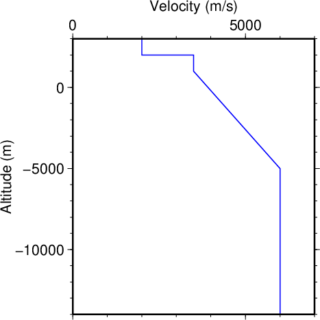
3000.0[TAB]2000.0
2000.0[TAB]2000.0
2000.0[TAB]3500.0
1000.0[TAB]3500.0
-5000.0[TAB]6000.0
-6400000.0[TAB]6000.0
このファイルによって表現される速度構造を図1に示す。 ファイルの書き方を示すために
を全て含む例として作成した架空の構造であり、 必ずしも現実的な構造ではない点に留意。
Fig. 1 shows the velocity structure represented by this file. This structure is imaginary, created for instruction of how to express:
Not that the structure is not necessarily realistic.


図1. 上記Vp.datで与えた速度構造。
Fig. 1. A velocity structure given by Vp.dat above.


◆検証(Validation)

このプログラムによって計算される深さは FDM_1D_verticalコマンドでの計算結果との比較によりチェックした。 手順と結果は以下の通り。
The depths computed by this program were examined by comparison with the results by FDM_1D_vertical command. The procedure and result are as follows.


●成層構造の場合 (In case of a stratified medium)

  1. 往復走時のリストを作成する。 ここでは往復走時のみあれば良いが、 列数が2列以上でなければならないので第2列にダミーの文字列を挿入する。 下記が作成したファイルである。
    Create a list of two-way travel times. Although only the two-way travel times are needed, the file must have at least two columns. To meet this requirement, dammy strings are inserted as the 2nd column. The example below shows the file created.

    traveltimes.dat
    0.01[TAB]Dammy
    0.02[TAB]Dammy
    0.03[TAB]Dammy

    5.00[TAB]Dammy

  2. 地下構造のファイル(twoWayTraveltime2depthコマンド用)を作成する。 ここでは以下のファイルを作成した。
    Create a file that represents a subsurface structure for twoWayTraveltime2depth command. The example below shows the file created.

    structure.ini
    500.0[TAB]2000.0
    0.0[TAB]2000.0
    0.0[TAB]3000.0
    -1000.0[TAB]3000.0
    -1000.0[TAB]4500.0
    -5000.0[TAB]4500.0
    -5000.0[TAB]6000.0
    -6400000.0[TAB]6000.0

    このファイルが表す速度構造を図2に示す。
    Fig. 2 shows the velocity structure expressed by this file.


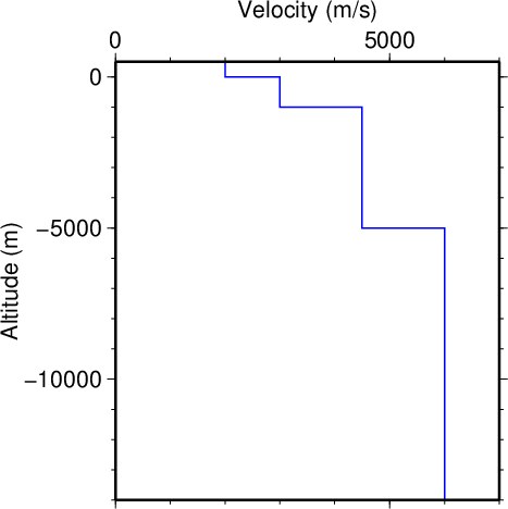
    図2. 上記structure.iniで与えた速度構造。
    Fig. 2. A velocity structure given by structure.ini above.

  3. twoWayTraveltime2depthコマンドを用いて往復走時を標高に変換する。 ここでは観測点(地表)を標高500 mに置く。 以下がそのコマンドである。
    Convert the two-way travel times to altitudes using twoWayTraveltime2depth command. Here, the station (ground surface) is plated at 500 m above sea level. The example below shows the command.

    twoWayTraveltime2depth traveltimes.dat altitudes.dat --mode=altitude --structure_file=structure.ini --station_altitude=500.0

    これにより、ファイルaltitudes.datが作成される。 その第1列が往復走時、第2列が標高を表す。
    This command creates a file altitudes.dat. The 1st and 2nd columns of this file represent two-way travel times and corresponding altitudes, respectively.

  4. 地下構造のファイル(FDM_1D_verticalコマンド用)を作成する。 図2と全く同じ速度構造であるが、 FDM_1D_verticalコマンド用に書き直すと以下のようになる。
    Create a file that represents a subsurface structure for FDM_1D_vertical command. Although this is exactly the same structure as Fig. 2, the file format is different; the file for FDM_1D_vertical command is shown below.

    structure_for_FDM.ini
    500.0[TAB]2000.0
    0.0[TAB]3000.0
    -1000.0[TAB]4500.0
    -5000.0[TAB]6000.0

  5. FDM_1D_verticalコマンドで入力として用いるボアホール観測点の波形を作成する。 ここでは時定数0.1 sのcos関数を作成する。 そのためのプログラムの例を以下に示す。
    Create the waveform at a borehole station used as the input for FDM_1D_vertical command. Here, a cos function with a time constant of 0.1 s is created. The example below shows a sample program to create this waveform.

    #include <inc.h>
    int main(void){
        struct sequence waveform=create_timefunc ("cos",0.1,0.0,200000,0.0,0.0001,0);
        write_sequence_file ("waveform_at_station_for_FDM.seq2",waveform);
    return 0;

    これを実行すると時定数0.1 sのcos関数が 時刻サンプル数200000、先頭時刻0.0 s、時間刻み0.0001 sで作成され、 ファイルwaveform_at_station_for_FDM.seq2に出力される。
    This code creates a file waveform_at_station_for_FDM.seq2 that represents a cos function with a time constant of 0.1 s, expressed by 200000 time samples beginning at 0.0 s and sampled at 0.0001 s intervals.

  6. FDM_1D_verticalコマンドを用いて波動場を計算する。 ここでは海抜下20 kmを計算領域の下端とし、 上で作成したwaveform_at_station_for_FDM.seq2を その場所での速度境界条件として与えて速度場の時空間発展を求める。 下記がそのためのコマンドの例である。
    Compute a wavefield using FDM_1D_vertical command. Here, the lower bound of the computational volume is placed at 20 km below sea level, where the waveform of waveform_at_station_for_FDM.seq2 created above is applied as a velocity boundary condition, to compute the spatiotemporal evolution of the velocity field. The example below shows a command to realize this computation.

    FDM_1D_vertical --structure_file=structure_for_FDM.ini --station_z=-20001.0 --inputfile=waveform_at_station_for_FDM.seq2 --outputfile=waveform_at_surface_by_FDM.seq2 --outputdir_snapshot=snapshot_by_FDM --dz=2.0 --dt=0.0001 --dt_snapshot=0.01 --tmax=10.0

    これにより、snapshot_by_FDMディレクトリが作成され、 その下に速度場のスナップショットが0.01 s間隔で出力される。
    This command creates a directory snapshot_by_FDM, below which the velocity snapshots at every 0.01 s are created.

上記FDM_1D_verticalコマンドで計算した速度場には この速度場には海抜下20 kmから上方に向かって伝播する波、 それが速度境界や地表で反射することで生じる下向きの波、 更にその後ろに多重反射波など様々な波群が含まれる。 ここではその中の地表で反射して下向きに伝播する波に注目する。 この波を含む時間帯の速度場を図3に示す。 4 s付近で地表を出発して6.3 s付近で海抜下10 kmに到達している波群が 地表からの反射波である。
The velocity field computed by the FDM_1D_vertical command above consists of various wave packets, including an upgoing wave from 20 km below sea level, downgoing waves caused by reflections at velocity discontinuities and the ground surface, and multiple reflected waves after them. Let us focus on the downgoing wave caused by the reflection at the ground surface. Fig. 3 shows the velocity field that consists of this wave packet. The wave packet that reaves the ground surface at ~4 s and arrives 10 km below sea level at ~6.3 s represents the downgoing wave caused by the reflection at the ground surface.

図3の黒線は twoWayTraveltime2depthコマンドを用いて計算した 往復走時と標高の関係(altitudes.dat)を 片道走時と標高の関係に直したものである。 スナップショットにおける下向きの反射波に合わせて時刻原点をずらしてある。 黒線とFDM_1D_verticalコマンドで計算した地表からの下向きの波(赤色)はよく合っており、 走時から標高への変換が正しく行えたことを示している。
The black line in Fig. 3 indicates a relation between one-way traveltimes and altitudes based on the results of the twoWayTraveltime2depth command; the two-way traveltimes in the file altitudes.dat created above were converted to one-way traveltimes, and the time origin was manually shifted to fit the reflected wave in the snapshot. The black line is well fitted to the downgoing wave from the ground surface computed by the FDM_1D_vertical command (red colors), indicating that the traveltimes were converted to altitudes correctly.


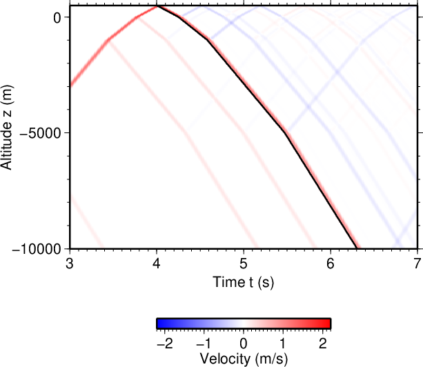
図3. FDM_1D_verticalコマンドで計算した波動場(カラー)と、 twoWayTraveltime2depthコマンドで計算した片道走時と標高の関係(黒線) との比較(図2の速度構造を用いたケース)。
Fig. 3. A comparison of the wave field computed by FDM_1D_vertical command (color) and a relation between one-way traveltimes and altitudes computed by twoWayTraveltime2depth command (the black line), in case of the subsurface structure shown in Fig. 2.


●地震波速度が標高の区分線形関数で与えられる場合 (In case where the seismic wave velocity is a piecewise linear function of the altitude)

この場合も手順はほぼ同じである。 地下構造ファイルを以下のように修正する。 この場合はtwoWayTraveltime2depthコマンド、FDM_1D_verticalコマンドとも 同じファイルを使用できる。
The procedure is almost same as above. Modify the file for the subsurface structure as follows; this file is used by both twoWayTraveltime2depth and FDM_1D_vertical commands.

structure.ini
500.0[TAB]2000.0
0.0[TAB]3000.0
-1000.0[TAB]4500.0
-5000.0[TAB]6000.0
-30000.0[TAB]7000.0

このファイルによって表現される速度構造を図7に示す。
Fig. 7 shows the velocity structure expressed by this file.


図4. 上記structure.iniで与えた速度構造。
Fig. 4. A velocity structure given by structure.ini above.

往復走時を標高に変換するtwoWayTraveltime2depthは 成層構造の場合と全く同じである。 FDM_1D_verticalコマンドは以下のように修正する。
The twoWayTraveltime2depth command for conversion of two-way traveltimes to depths is exactly same as that for the stratified medium. Modify the FDM_1D_vertical command as below.

FDM_1D_vertical --structure_file_format=linear --structure_file=structure.ini --station_z=-20001.0 --inputfile=waveform_at_station_for_FDM.seq2 --outputfile=waveform_at_surface_by_FDM.seq2 --outputdir_snapshot=snapshot_by_FDM --dz=2.0 --dt=0.0001 --dt_snapshot=0.01 --tmax=10.0

計算結果を図3と同じ要領で比較したものが図5である。 この場合にも黒線(twoWayTraveltime2depthコマンドの結果)は 地表から下向きに伝播する波群(赤色、FDM_1D_verticalコマンドの結果)とよく合っており、 走時から標高に正しく変換できたことが分かる。
Fig. 5 shows a comparison of the results in the same manner as Fig. 3. Again the black line (the result of twoWayTraveltime2depth command) well explains the downgoing wave packet from the ground surface (red color; the result of FDM_1D_vertical command), indicating that the traveltimes were converted to altitudes correctly.


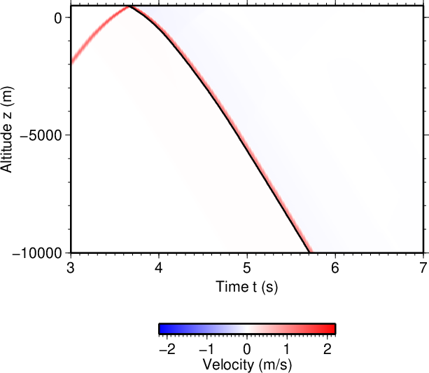
図5. FDM_1D_verticalコマンドで計算した波動場(カラー)と、 twoWayTraveltime2depthコマンドで計算した片道走時と標高の関係(黒線) との比較(図4の速度構造を用いたケース)。
Fig. 5. A comparison of the wave field computed by FDM_1D_vertical command (color) and a relation between one-way traveltimes and altitudes computed by twoWayTraveltime2depth command (the black line), in case of the subsurface structure shown in Fig. 4.


◆追加の情報 (Additional information)