パラメータ名
Parameter name
|
意味
Meaning
|
可能なパラメータ値
Allowed parameter values
|
デフォルト値
Default value
|
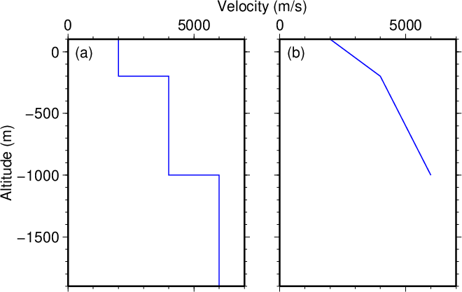
| structure_file_format |
使用する地下構造の種類。
Type of the subsurface structure used.
|
- stratified
深さ範囲毎に一定の速度値を持つ成層構造。
A stratified medium that has a constant velocity
in each section of depth ranges.
- linear
深さの区分線形関数で速度値が変化する構造。
A medium with the velocity that increases
as a piecewise linear function of depth.
|
stratified |
| structure_file |
使用する地下構造ファイル名。
The name of a file for the subsurface structure used.
ファイルの書式は以下の通りとする。
The format of this file is as follows.
|
ファイル名を表す文字列。
A string that represents a file name.
|
省略不可
Cannot be omitted |
| station_z |
ボアホール観測点の標高[m](上向きを正)。
このプログラムでは観測点が計算領域下端になる点に留意。
The altitude [m] (positive: upward) of the borehole station.
Note that the station is
at the lower bound of the computational volume
in this program.
|
実数値。
地表面の標高(地下構造ファイルの第1行)よりも小さくなければならない。
また地震波速度を深さの区分線形関数で与える場合
(structure_file_format=linear)
には地下構造ファイルの最終行が地震波速度の定義域の下限となるので
この値以上でなければならない。
A real number less than the ground surface altitude
given by the 1st line of the structure file.
In cases where the seismic velocity is given
as a piecewise linear function of depth
(structure_file_format=linear) ,
the station altitude must be greater than or equal to
the altitude in the final line of the structure file
that represents the lower bound of the definition range
of the velocity structure.
| 省略不可
Cannot be omitted |
| inputfile |
ボアホール観測点での速度波形のファイル名。
いずれか1つの成分(上下動又は水平動)の波形を与える。
The name of file that represents the velocity waveform
at the borehole station;
either a vertical or a horizontal component.
- Seismic Analysis Code (SAC)の時系列データ、
またはymaeda_opentoolsの時系列データ
(独自のファイル形式参照)
とする。
The file format must be a time series data of
the Seismic Analysis Code (SAC)
or a time series data format of ymaeda_opentools
(see
Special file formats).
- 波形は時刻の単位が[s]、振幅の単位が[m/s]でなければならない。
The time and amplitude of the waveform
must be expressed in [s] and [m/s], respectively.
- サンプル数は偶数でなければならない。
The number of samples must be an even number.
|
ファイル名を表す文字列。
拡張子によってファイル形式が判別される。
aseq1, aseq2は未対応。
SAC形式の場合は拡張子を小文字の「.sac」とすること。
A string that represents a file name.
The file format is automatically identified
based on the extention of the file name.
The aseq1 and aseq2 formats are not supported.
In case of a SAC format,
use “.sac” (small letters)
for the extension.
|
省略不可
Cannot be omitted |
| outputfile |
計算した地表での波形の出力先ファイル名。
The name of an output file for
the waveform at the ground surface computed.
- ymaeda_opentoolsの時系列データのファイル形式
(独自のファイル形式参照)
とする。
The file format must be a time series data format
of ymaeda_opentools
(see
Special file formats).
- ボアホール観測点(パラメータinputfile)と同じ成分の波形が
時刻の単位を[s]、振幅の単位を[m/s]として出力される。
The component of the output waveform is same as
that of the borehole station given by parameter inputfile.
Units of time and amplitude are [s] and [m/s], respectively.
|
ファイル名を表す文字列。
拡張子はymaeda_opentoolsの時系列データファイル用のもので
なければならない。
aseq1, aseq2は未対応。
A string that represents a file name,
which ends with an extension that corresponds to
a time series data format of ymaeda_opentools
other than aseq1 and aseq2.
|
省略不可
Cannot be omitted |
| outputfile_station |
実際に計算に使用したボアホール観測点での波形の出力先ファイル名。
計算ではパラメータinputfileで指定したファイルの波形が
そのまま用いられるわけではなく、
差分計算の時間刻み\(\Delta t\)に合わせて補間した波形が用いられる。
その補間した波形がチェック用に
このパラメータで指定したファイルに出力される。
The name of an output file for
the waveform at the borehole station that was actually used.
In the computation,
the waveform in the file specified by parameter inputfile
is not used directly;
instead, a waveform interpolated to
a sampling rate of the FDM computation (\(\Delta t\)) is used.
This interpolated waveform is written into the file
specified by this parameter for check.
|
ファイル名を表す文字列。
拡張子はymaeda_opentoolsの時系列データファイル用のもので
なければならない。
aseq1, aseq2は未対応。
A string that represents a file name,
which ends with an extension that corresponds to
a time series data format of ymaeda_opentools
other than aseq1 and aseq2.
|
省略時はこの波形が出力されない。
This waveform is not written when this option is omitted.
|
| outputdir_snapshot |
速度場のスナップショットの出力先ディレクトリ名。
The name of a directory to output
the snapshots of the velocity field.
|
ディレクトリ名を表す文字列。
A string that represents a directory name.
|
省略時はスナップショットが出力されない。
The snapshots are not created when this option is omitted.
|
| dz |
差分計算に用いるグリッド間隔\(\Delta z\)[m]。
The grid interval \(\Delta z\) [m]
used for the FDM computation.
下記「検証」で示すように
差分計算で通常考えられているよりも
かなり細かいグリッド刻みが必要であり、
数値テストの結果からはナイキスト周波数に対応する波長の中に
200グリッド以上が入ることが望ましい。
The grid interval should be substantially smaller than
that normally considered in FDM calculations;
numerical tests suggest that at least 200 grids in one wavelength
of the Nyquist frequency is desiable
as shown in the “Validation” section below.
|
正の実数。
staggered gridにおいてボアホール観測点(計算領域下端)で速度、
地表(計算領域上端)で応力が定義されるように、
地表とボアホール観測点の標高差を\(\Delta z\)で割った値が
整数値\(+1/2\)となるように与えなければならない。
A positive real number that satisfies a requirement that
the altitude difference
between the ground surface and the borehole station
is an integer \(+1/2\);
this requirement is to enable
the velocity and stress to be defined at
the borehole station and ground surface,
which corresponds to the lower and upper bounds
of the computational volume, respectively.
|
観測波形の時間刻みに地震波速度の最小値を掛けた値の1/200未満の
可能な最大の\(\Delta z\)。
The maximum possible \(\Delta z\) less than 1/200 of
the time stepping of the observed waveform
multiplied by the minimum seismic wave velocity.
|
| dt |
差分計算に用いる時間刻み\(\Delta t\)[s]。
The time stepping \(\Delta t\) [s]
used for the FDM computation.
|
正の実数。
地震波速度の最大値を\(V_{max}\)として
\(\Delta t<\Delta z/(\sqrt{3}V_{max})\)でなければならない。
また観測波形の時間刻みの整数分の1でなければならない。
A positive real number
that satisfies \(\Delta t<\Delta z/(\sqrt{3}V_{max})\),
where \(V_{max}\) is the maximum seismic wave velocity.
Also, the value must be a divisor of
the time stepping of the observed waveform.
|
\(\Delta t<\Delta z/(\sqrt{3}V_{max})\)の条件を満たし、
観測波形の時間刻みの整数分の1かつ有限桁の小数で表現可能な
最大の\(\Delta t\)。
The maximum possible \(\Delta t\)
that satisfies \(\Delta t<\Delta z/(\sqrt{3}V_{max})\)
and is divisor of the time stepping of the observed waveform
expressed by a finite number of decimal digits.
|
| dt_snapshot |
スナップショットを出力する時間間隔[s]。
The time interval [s] to output the snapshots.
|
正の実数。パラメータdtの値の整数倍でなければならない。
A positive real number
that is an integer multiple of
the value of parameter dt.
|
観測波形(パラメータinputfile)の時間刻み。
The sampling interval of the observed waveform
specified by parameter inputfile.
|
| tmax |
計算する波形の時間長さ[s]。
Time length [s] of the waveform to compute.
|
\(\Delta t\)以上かつ観測波形の長さ以下の正の実数。
A positive real number
greater than or equal to \(\Delta t\)
and less than or equal to the length of the observed waveform.
|
観測波形の長さ。
The length of the observed waveform.
|