パラメータ名
Parameter name
|
意味
Meaning
|
可能なパラメータ値
Allowed parameter values
|
デフォルト値
Default value
|
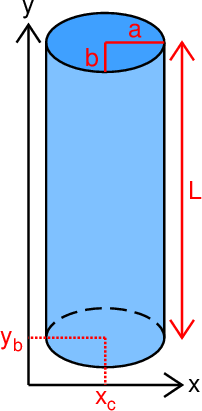
| center_x |
円筒の中心軸の\(x\)座標\(x_c\)。
The \(x\)-coordinate of the central axis of the cylinder \(x_c\).
|
実数。
A real number.
|
0.0 |
| longer_radius |
円筒の上面・下面を表す楕円の長軸半径\(a\)(図1)。
The longer radius \(a\) of the ellipsoids that represent
the roof and bottom surfaces of the cylinder (Fig. 1).
|
正の実数。
A positive real number.
|
1.0 |
| shorter_radius |
円筒の上面・下面を表す楕円の短軸半径\(b\)(図1)。
The shorter radius \(b\) of the ellipsoids that represent
the roof and bottom surfaces of the cylinder (Fig. 1).
|
\(a\)よりも小さな正の実数。
A positive real number less than \(a\).
|
\(a/2\) |
| angle_interval |
描画する楕円上の点の角度刻み\(\Delta\theta\)(°)。
The angle interval \(\Delta\theta\) (°)
of the points to draw the ellipsoid.
|
180.0の整数(\(\geq 2\))分の1となる正の実数。
A positive real number that is
an integer (\(\geq 2\)) divisor of 180.0.
|
1.0 |
| bottom_y |
円筒の下面を表す楕円(図1)の中心点の\(y\)座標\(y_b\)。
The \(y\)-coordinate of the center of the ellipsoid \(y_b\)
that represents the bottom surface of the cylinder (Fig. 1).
|
実数。
A real number.
|
0.0 |
| length |
円筒の長さ\(L\)。
The length \(L\) of the cylinder.
|
\(2b\)よりも大きな正の実数。
A positive real number greater than \(2b\).
|
\(10b\) |